Transformer Wiring Diagram

Transformer Wiring Diagram transformer An ideal transformer is a theoretical linear transformer that is lossless and perfectly coupled Perfect coupling implies infinitely high core magnetic permeability and winding inductances and zero net magnetomotive force Transformer Wiring Diagram daltco files resource schneider wiring diagram book pdf Fi ier PDFWiring Diagram Book A1 15 B1 B2 16 18 B3 A2 B1 B3 15 Supply voltage 16 18 L M H 2 Levels B2 L1 F U 1 460 V F U 2 L2 L3 GND H1 H3 H2 H4 F U 3 X1A F U 4 F U 5 X2A R Power On Optional
pump thermostat wiring chart Heat Pump Thermostat Wiring Chart Diagram The Basic heat pump wiring for a heat pump thermostat is illustrated above It corresponds with the chart Transformer Wiring Diagram rv52 nice 50 amp receptacle voltage diagramThis article has a great 50 amp rv plug diagram The diagram is simple to read and easy to use Make sure you use this to check voltages BEFORE connecting generatorsforhomeuse electrical wiringThe basics of home electrical wiring A diagram of a single phase 120 240V service
electricalonline4u 2015 09 contactor wiring diagram htmlcontactor wiring for 3 phase motor with images and diagram Transformer Wiring Diagram generatorsforhomeuse electrical wiringThe basics of home electrical wiring A diagram of a single phase 120 240V service gemremotes pdfs GEM wiring diagram 1 07 pdf Fi ier PDFL1 3 4 L2 BALDOR Wired at 115VAC Wiring From GEM Unit From Motor Windings Motor Brown J Motor Red TT88 Motor White T2 Motor Blk T5 GEM Blk GEM Red Gem White GEM Org To change motor direction
Transformer Wiring Diagram Gallery
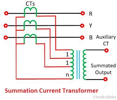
summation transformer circuit diagram, image source: circuitglobe.com

homebuilt arc welder dans workshop blog pertaining to welding machine wiring diagram pdf, image source: tops-stars.com
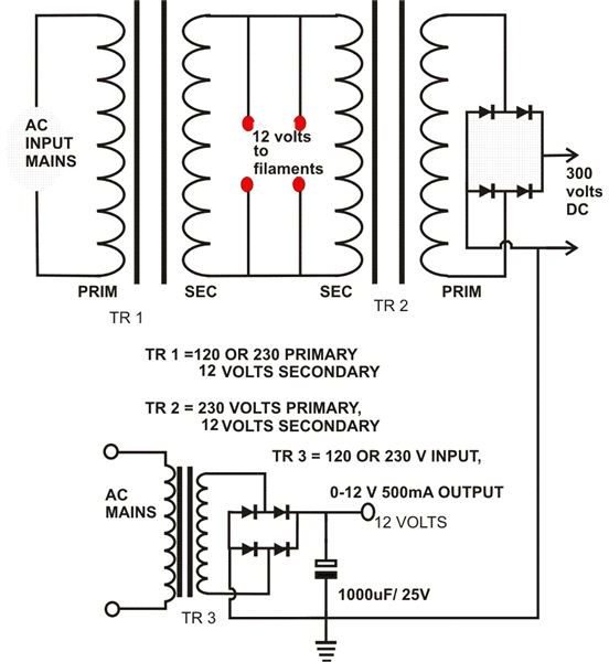
5a9a76463fe87bbf80cae89baca45a2c828fdc1f_large, image source: www.brighthubengineering.com
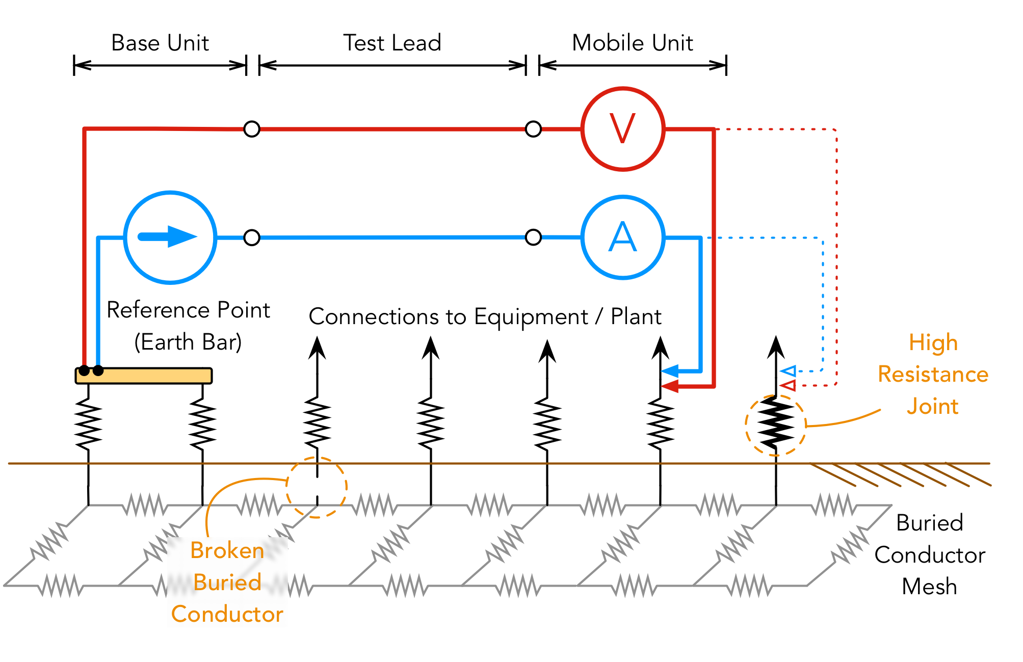
Integrity Article Picture 300, image source: www.safearth.com
rain bird cad detail drawings controllers of rain bird sst600i wiring diagram 2, image source: bioart.me
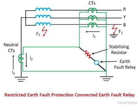
restricted earth fault relay protection of star coonected neutral grounded side, image source: circuitglobe.com

flyback, image source: www.nuffzedd.com
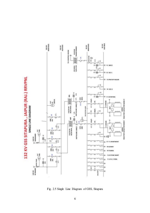
132kv gss report of sitapura jaipur 6 638, image source: www.slideshare.net

Twisted Pair AlDmour, image source: www.researchgate.net

maxresdefault, image source: www.youtube.com
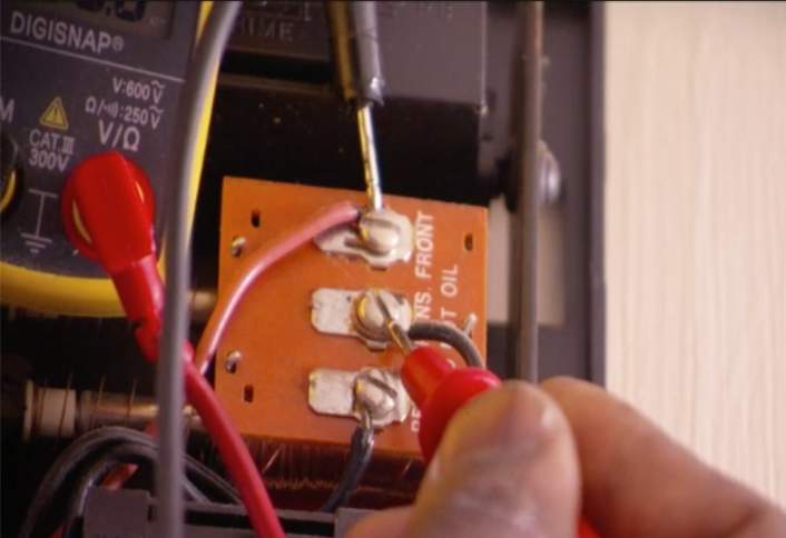
how to replace a doorbell button HT PG EL step 02b, image source: www.homedepot.com
labeled, image source: www.righto.com
component electrical heater symbol electric isa symbols ieee std quick reference only duct re_electric symbol_symbols of electricity for electronics thermistor symbol speaker domestic e, image source: farhek.com
20_watt_push pull_CFL_inverter_circuit_diagram 1024x549, image source: www.circuitsdiy.com

maxresdefault, image source: www.youtube.com
![]()
solar tracking system 7 638, image source: www.slideshare.net

HTB19rirIpXXXXc6aXXXq6xXFXXXO, image source: www.alibaba.com

maxresdefault, image source: www.youtube.com

61XCP8j3VNL, image source: thetada.com
Comments
Post a Comment