2 Port Valve Wiring Diagram
2 Port Valve Wiring Diagram dtafast uk download files Wiring Diagrams Fi ier PDFwiring schematic for s40pro last updated 18 11 2014 needs firmware v77 00 and higher 1 2 3 4 5 6 7 8 9 10 1 12 13 14 15 16 17 18 19 20 21 22 23 24 25 2 Port Valve Wiring Diagram emerson documents automation instruction Fi ier PDFFisher Fisher D3 Control Valve with Gen 2 easy Drive Electric Actuator Contents Introduction 1 Scope of Manual 1
efi parts uk index php show aux page 9Adaptronic E420C E420D 440 and Select wiring diagrams by EFI Parts 2 Port Valve Wiring Diagram electriciansblog uk 2011 11 how does a y plan central This article shows a diagram and explains the internal workings of the 3 Port Mid Position Motorised Valve as used in Y Plan and Biflow central heating systems megamanual v22manual mwire htmThis provides a direct signal from the MegaSquirt EFI controller to the PWM idle valve Note that the transistor on the V3 main board is NOT sufficient to drive a Ford PWM Idle valve as well as many other makes directly
trucks forums 1062216 2004 full color wiring 6 15 2017 Ranger B Series 2004 Full color Wiring Diagram A couple of years ago I ordered a set of 2004 Full Color Wiring it s PDF file diagrams from Automotive Hobbyists who have since gone out of business and I was wondering if 2 Port Valve Wiring Diagram megamanual v22manual mwire htmThis provides a direct signal from the MegaSquirt EFI controller to the PWM idle valve Note that the transistor on the V3 main board is NOT sufficient to drive a Ford PWM Idle valve as well as many other makes directly valvechatter p 2313Pump reservoir pump bracket fixing kit fuse box connector blocks wiring connectors alternator pulley single or double fitting kit steering rack rack brackets rack bushes track rod ends racking fitting kit column tube steering pipes instructions a cutting template and a wiring diagram
2 Port Valve Wiring Diagram Gallery

honeywell 2 port valve wiring diagram 5a23194ed965b, image source: fitfathers.me
th?id=OGC, image source: codecookbook.co

3 phase ac contactor wiring diagram 3 phase contactor wiring intended for mechanically held lighting contactor wiring diagram, image source: www.diaoyurcom.com

boiler wiring diagram for thermostat to y plan wiring diagram hive, image source: estrategys.co

phenomenal 3 wire alternator wiring diagram 4, image source: dejual.com
Yplan, image source: jeffdoedesign.com
1251376013_sys03 a, image source: www.odicis.org
th?id=OGC, image source: www.projectsinmetal.com

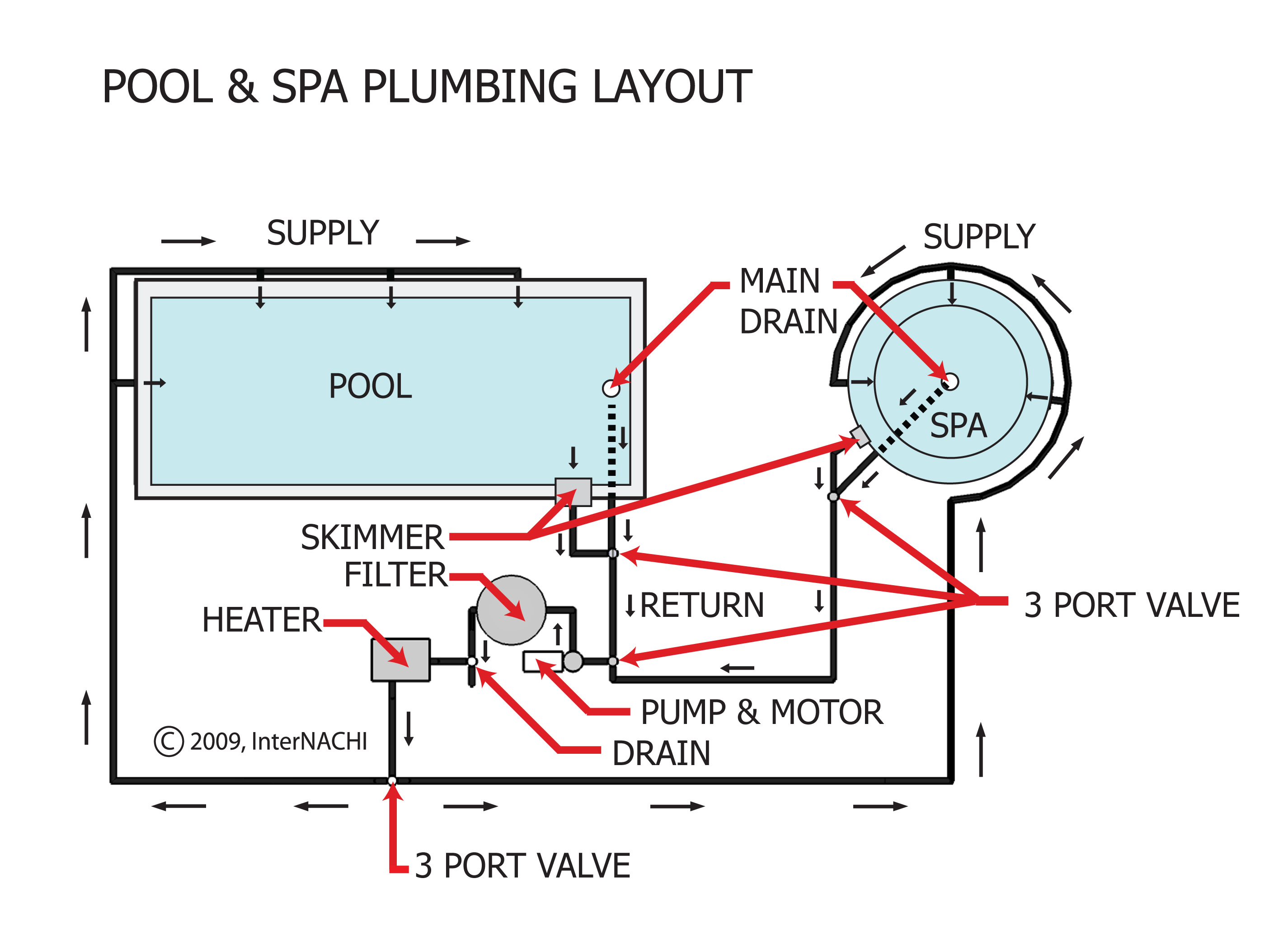
pool spay plumbing layout 3, image source: www.nachi.org

4_cycle_schem_640px, image source: www.amsoil.com

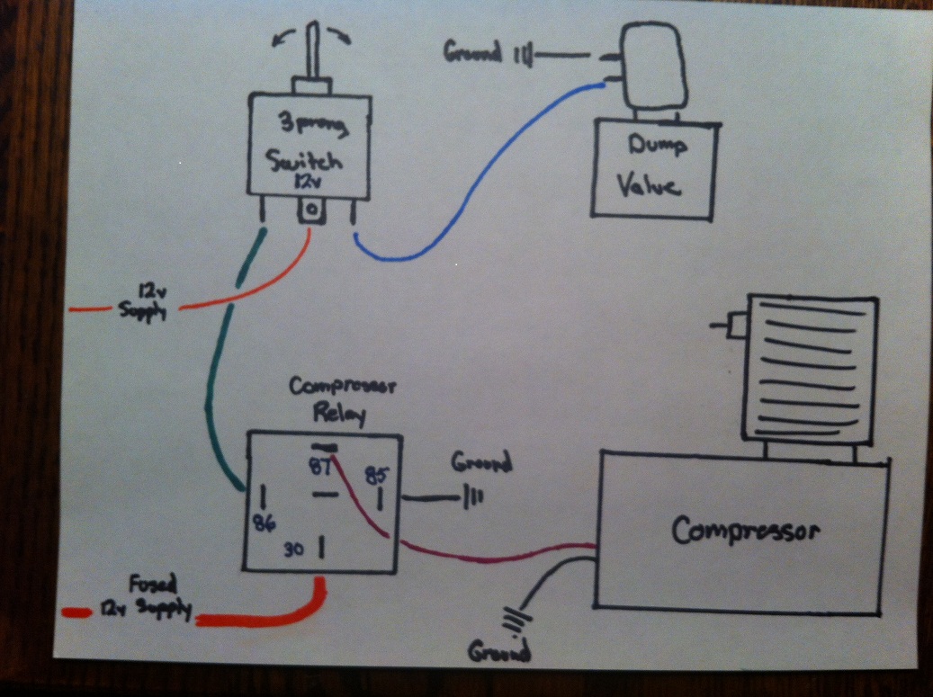
461155d1456292901 diy air ride wiring help 003, image source: www.hdforums.com

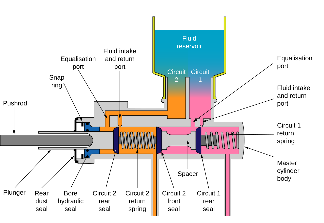
1280px Master_cylinder_diagram, image source: commons.wikimedia.org
fiesta_st_ATP_ChargePipe_Diagram, image source: www.atpturbo.com
3_Flexfuelsensorwiring, image source: www.adaptronic.com.au

maxresdefault, image source: www.youtube.com

maxresdefault, image source: www.youtube.com

2010 06 03_120005_1, image source: www.justanswer.com
, image source: www.plowsite.com
Comments
Post a Comment